
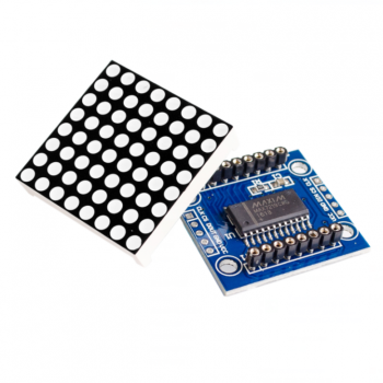


MAX7219 Dot Matrix Module Microcontroller Module
The MAX7219 8×8 Dot Matrix Red Display Module Kit has a 1.3″ 64 LED dot matrix display with built-in MAX7219 serial LED driver.
PACKAGE INCLUDES:
- 1.3″ 8 x 8 dot matrix of red LEDs
- MAX7219 LED Driver board
- 8-pin female socket (x2)
- 5-pin right-angle male header
- 5-pin right-angle or straight male header
Availability: In Stock
KEY FEATURES OF MAX7219 8×8 DOT MATRIX RED DISPLAY MODULE KIT:
- Single 8×8 LED Matrix Display with 1.3″ high bright red display
- Built-in MAX7219 LED Driver
- SPI 3-wire serial interface for easy hookup to MCU
- Can daisy-chain multiple modules together for larger displays
- Kit comes with IC soldered. Just need to add connectors and plug in the display module
- 5V Operation
MAX7219 LED Driver
The MAX7219 is a popular and flexible 7-segment, bar graph and dot matrix common cathode LED driver that supports many functions for controlling LED displays.
The driver provides flexible individual LED control as well as basic functions such as turning the display ON/OFF and adjusting the LED brightness.
The MAX7219 communicates with a MCU via a 3-wire SPI bus. Once the display is updated by the MCU, the MAX7219 then takes care of all the work of keeping the display refreshed, so it removes that overhead from the MCU which can be off doing other more important things.
SPI Interface
The module communicates via the SPI interface, so it only requires 3 data pins to connect to a MCU.
If a larger display is needed, several modules can be daisy-chained together.
Libraries are readily available such as the “LedControl.h” library built-in to the IDE for Arduino that makes communicating with the display very straightforward.
Module Connections
There is an input header on one end for connection to an MCU and output header on the other end for connecting to additional modules.
Input Connector
The header pins on the “IN” side is the main input connector. “Vcc” connects to 5V. Due to the fairly high current draw of the display (up to 250mA if the brightness is cranked all the way up), it is recommended to keep the brightness turned down to < 50% to avoid overheating the MCU voltage regulator if there are other peripherals also attached to this supply. “GND” connects to ground which needs to be common with the MCU.
The other pins are for the SPI interface. “DIN” is the Data In. “CS” is Chip Select (sometimes labeled as LOAD) and “CLK is the Clock pin. These lasts 3 pins are connected to any digital outputs on the microcontroller. Which pins they connect to is defined when an instance of the LedControl is created as shown in the program below.
1 x 5 Header
- VCC – Connect to 5V.
- GND – Connect to system ground. This ground needs to be in common with the MCU.
- DIN – Connect to any digital pin on MCU.
- CS / LOAD – Connect to any digital pin on
- CLK – Connect to any digital pin on MCU.
Output Connector
The break-out pins on the other end of the assembly are used if it is desirable to daisy-chain multiple displays. In this case, the “DOUT” is Data Out and it connects to the next modules “DIN” Data in pin. The other pins are passed straight-thru
1 x 5 Header
- VCC – Connect to 5V on next module if looping power through.
- GND – Connect to GND on next module
- DOUT – Connect to DIN on next module.
- CS / LOAD – Connect to CS / LOAD on next module
- CLK – Connect to CLK on next module
Assembling Module
This comes as a kit that requires some soldering in order to complete, but all the hard stuff is already done such as mounting the MAX7219 IC and other surface mounted devices.
The kit may come with a right-angle header and a straight header or it may come with two right-angle headers.
- Be the first to review this product
WRITE YOUR OWN REVIEW
How do you rate this product? *